Current-Starved VCO
The principle of this VCO lies in control of the inverters supply, thus controlling the oscillation frequency of the inverter based ring oscillator.
Design
I used 5 inverter stages in this design. The schematic is below
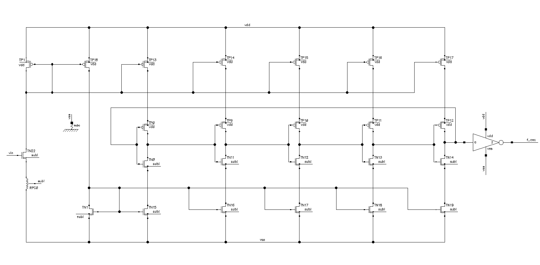
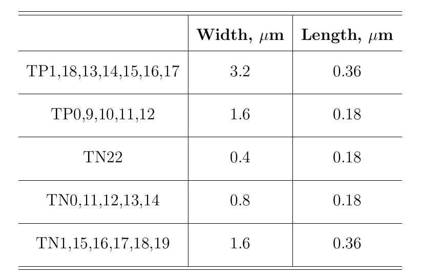
Transistor sizes I used are shown below
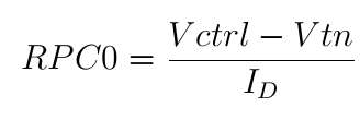
The design primarily consists of computing the required current based on the node capacitance in between the inverters, frequency of oscillation and setting properly the biasing resistor RPC0


In this case the design was optimized for usage in the 1.2 GHz fixed frequency PLL.
Simulation
Below is the Kvco parameter simulation plot
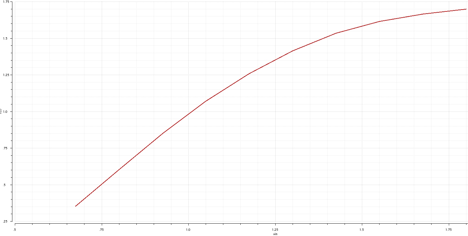
Below is a zoomed plot with markers at +/- 10 MHz around the main frequency
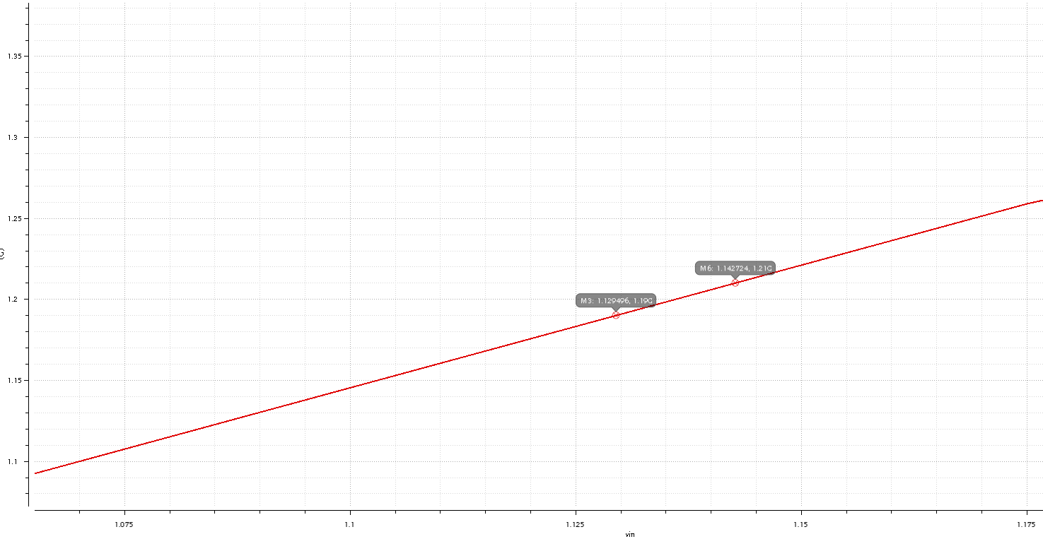
Now I can compute my Kvco as

Below is a Phase Noise plot from PSS simulation
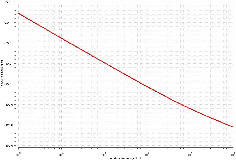
Looks pretty noisy, but well, this is a ring oscillator based VCO, which is very compact from the layout point of view but too noisy.
I will perform later more work on minimization of the phase noise of ring based VCO.

