256 Point FFT core integration project
I had to integrate some 256 point Fast-Fourier Transform code into a digital implementation for the 180nm IBM 7RF process for some project. Since this particular design was more of a design flow and technology test, I just decided to use some available free core, given the fact that 256 point FFT is not a long and challenging transform.
I decided to use a core available from Unicore Systems.
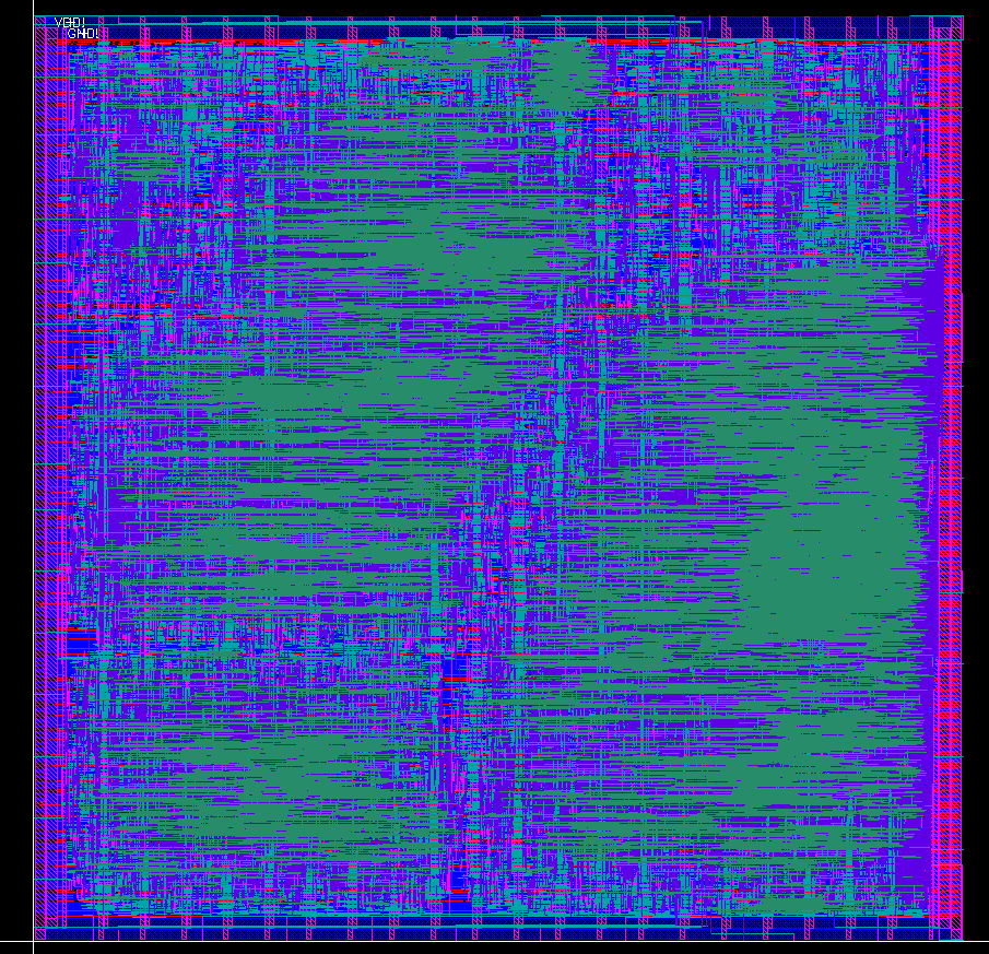
I wrote a top level automated Verilog testbench for that core which tested it with different type of input vectors and had MATLAB analyze the output results. After that I passed that code through the Cadence Digital Implementation system, had it auto placed and autorouted. The result is shown below.

The standard cells are aligned as horizontal rows with the horizonal power lines running from one side of the frame to another. There are also 10um wide power and ground vertical lines repeating every 100um, they can be seen on top and bottom parts of the design in pink color, they are implemented on M2 level metal.The maximum routing layer is M5. Total size of design is roughly 2200um x 2200um. The design also has an amoeba clock tree and was tweaked to meet the timing at 100 MHz main clock.
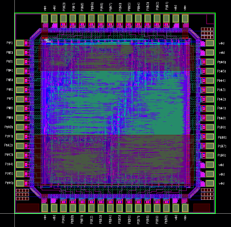
After that I designed the custom Pad Frame for 3mm x 3mm size with input digital buffers, strong output digital buffers and decoupling capacitors and integrated the autorouted design into my pad frame as shown below.

The design was submitted for manufacturing through the MOSIS service.

